Ohm's Law Series-Parallel Circuits Calculation

To end up the discussion of Series-Parallel Circuits, I would like to post this last one remaining topic which is about Ohm's Law of Series-Parallel Circuits for currents and voltages. I did not even mentioned in my previous topics on how to deal with its currents and voltages regarding this type of circuit connection. 


Ohms Law in Series-Parallel Circuits

Ohm's Law in Series-Parallel Circuits - Current

The total current of the series-parallel circuits depends on the total resistance offered by the circuit when connected across the voltage source. The current flow in the entire circuit and it will divide to flow through parallel branches. In case of parallel branch, the current is inversely proportional to the resistance of the branch - that is the greater current flows through the least resistance and vice-versa. Then, the current will then sum up again after flowing in different circuit branch which is the same as the current source or total current.

The total circuit current is the same at each end of a series-parallel circuit, and is equal to the current flow through the voltage source.


Ohm's Law in Series-Parallel Circuits - Voltage

The voltage drop across a series-parallel circuits also occur the same way as in series and parallel circuits. In series parts of the circuit, the voltage drop depends on the individual values of the resistors. In parallel parts of the circuit, the voltage across each branch are the same and carries a current depends on the individual values of the resistors. 

If in case of circuit below, the voltage of the series resistance forming a branch of the parallel circuit will divide the voltage across the parallel circuit. If in case of the single resistance in a parallel branch, the voltage across is the same as the sum of the voltages of the series resistances.

The sum of the voltage across R3 and R4 is the same
as the voltage across R2.

Finally, the sum of the voltage drop across each paths between the two terminal of the series-parallel circuit is the same as the total voltage applied to the circuit.

Let's have a very simple example of this calculation for this topic. Considering the circuit below with its given values, lets calculate the total current, current and voltage drop across each resistances.


What is the total current, current and voltage across each resistances
 Here is the simple calculation of the circuit above:

a. Calculate first the total resistance of the circuit:

The equivalent resistance for R2 and R3 is:

R2-3 = 25X50/ 25+50 = 16.67 ohms

R total =  30 ohms + 16.67 ohms = 46.67 ohms

b. Calculate the Total Current using Ohm's Law:

I1 = 120V / 46.67 Ohms = 2.57 Amp. Since R1 is in series connection, the total current is the same for that path.

c. Calculating the voltage drop for R1:

VR1 = 2.57 Amp x 30 ohms = 77.1 volts

d. Calculate the voltage drop across R2 and R3.

Since the equivalent resistance for R2 and R3 as calculated above is 16.67 ohms, we can now calculate the voltage across each branch.

VR2 = VR3 = 2.57 Amp x 16.67 ohms = 42. 84 volts

e. Finally, we can now calculate the individual current for R2 and R3:

I2 = VR2 / R2 = 42.84 volts / 25 ohms =  1.71 Amp.
I3 = VR3 / R3 = 42.84 volts / 50 ohms = 0.86 Amp.

You may also check if the current in each path of the parallel branch are correct by adding its currents:

I1 = I2 + I3 = 1.71 Amp + 0.86 Amp = 2.57 Amp. which is the same as calculated above. Therefore, we can say that our answer is correct.


Cheers!
readmore »»   http://img.ezinemark.com/imagemanager2/files/30004252/2011/11/E10.jpg

The Bridge Resistor Circuit

This is already the Part-3 lessons for Series-Parallel Circuits. Today we will be dealing with another type of complex circuit which you do not know yet - particularly for the beginners.

Suppose you have a type of simple circuit below. You will notice that there is an extra resistor of R3 connecting to the two parallel branches of the parallel circuit connection and in such way it was interrupted to the leads of the new resistor. This new resistor (R3) is called a bridge.
R3 is called the Bridge Resistor
 Take a look at the circuit above. If you look at the upper part of R3 resistor, wherein R1, R2 and R3 are all connected together. You will notice a new arrangement of connection. This arrangement from its similarity to the shape of the Greek letter D (delta), is said to be delta connected. Here is the diagram below to see clearly what I'm talking about.
This is the illustrative diagram for delta connection


The equivalent connection of left diagram is
called the Y connection 
 Take a look at the diagram at the left side. If you will devise a circuit shown in the delta connection Ra, Rb and Rc to shaped like a Y (wye). This Y circuit would fit onto the rest of the original circuit in such a way that you could solve its values without difficulty. Look at the diagram (at the left)  in Y connection.

The resistors connected in Y are R1, R2 and R3. Take note that their values must be such that the terminal resistances at N1 and N3 are exactly where they were in the original circuit. The problem now is how would you able to solve the values of R1, R2 and R3 (said to be unknown values) in terms of Ra, Rb and Rc whose values are known.

How to Solve Bridge Resistor Circuit

Lets use again this previous diagram. Then, take note that both circuits must give exactly the same values of resistance across every corresponding pair of terminals. This operation that we'll set is called delta-Y conversion or transformation.

delta -Y conversion
 If you consider the sum of the resistances between N3 and N1, then assume N2 is to be disconnected. In delta combination you will see that between these two points there is a series combination of Rc and Rb in parallel across Ra. You can now express the resistance N3 and N1 applying the knowledge of parallel circuits we have:

Ra (Rb + Rc) / Ra + Rb + Rc

Considering the Y circuit connection above, the total resistance between N3 and N1 is R1 + R3. Then, since we all know that these resistances must be equal, you can now write down the first equation as:

R1 + R3 = Ra (Rb + Rc)/ Ra + Rb + Rc   ---------> EQUATION no. 1

For the remaining terminals, you can exactly do the same way for total resistances between N3 - N2 and between N1 - N2 in terms of Ra, Rb, Rc and R1, R2 and R3. Then, you will get the two remaining equations: 

R2 + R3 = Rc (Ra + Rb) / Ra + Rb + Rc  ---------> EQUATION no. 2

R1 + R2 = Rb (Ra + Rc) / Ra + Rb + Rc  ---------> EQUATION no. 3

Then, do a little algebra from the three equations above to obtain the values in terms of R1, R2 and R3. Finally, we can have the following formula:

R1 = Ra x Rb / Ra + Rb + Rc ------------> Formula no. 1

R2 = Rb x Rc / Ra + Rb + Rc ------------> Formula no. 2

R3 = Ra x Rc / Ra + Rb + Rc ------------> Formula no. 3

The problem below was given in the board exam way back 1997 - two years before my  EE board examination.

(EE April'97) A circuit consisting of three resistors rated : 10 ohms, 15 ohms and 20 ohms are connected in DELTA. What would be the resistances of the equivalent WYE connected load?

Solution:
Just get the pattern of the above formula, this would give us the following:

R1 = 10 X 15 / 10 + 15 + 20 = 3. 33 ohms - answer

R2 = 15 x 20 / 10 + 15 + 20 = 6. 67 ohms - answer

R3 = 10 X 20 / 10 + 15 + 20 = 4.44 ohms - answer


Y to Delta Conversion

For the reverse conversion which is Y to delta conversion considering the given circuit.

Y to delta conversion or transformation

The general idea here is to compute the resistance in the delta circuit by:

R- delta = Rp / R opposite

where: Rp is the sum of the product of all pairs of resistances in the Y circuit and R opposite is the resistance of the node in the Y circuit which is opposite the edge with R- delta. You will have the following formula for you to get the equivalent delta load in terms of Ra, Rb and Rc.

Ra = R1R2 + R2R3 + R3R1 / R2 ---------> Formula no. 4

Rb = R1R2 + R2R3 + R3R1 / R3 ---------> Formula no. 5

Rc = R1R2 + R2R3 + R3R1 / R1  ---------> Formula no. 6

These are the formula that you'll going to use from our future topics since this is already the part of Network Theorems. Don't ever forget it...

Cheers!
readmore »»   http://img.ezinemark.com/imagemanager2/files/30004252/2011/11/E10.jpg

Series-Parallel Circuits- Part 2

This is just the continuation of my post yesterday about Series-Parallel Circuits- Part 1. I've already provided you the steps on how to simplify a simple series-parallel connections. Today, I will give you an example on how to solve that circuit using that steps mentioned before.

The practical example that I will show you below is how to break down a complex circuits to find the total resistance. Refer to figure below:

Circuit Problem for Series-Parallel
Let's say:  R1= 7 ohms, R2= 10 ohms, R3= 6 ohms and R4= 4 ohms. We are required to get the total resistance of the circuit.

Using the steps that previously discussed here. We can redraw an equivalent circuit in a way that we can understand it well. The figure below is the redrawn circuit for the given problem above.

1. Redraw the circuit.

Redrawn Series-Parallel
From the redrawn circuit above. we can now simplify R3 and R4. Lets name it R3-4 = 6+4 = 10 ohms.

2. The next step is by getting the resistance between R2 and R3-4 connected in parallel. The circuit now will be simplify as shown below:

Simplified R3-4 to be combine with R2
Next, we will simplify the R2 and R3-4 using the formula of two resistances connected in parallel. Let's name it Ra= R2 X R3-4 / R2 + R3-4 = 10 x 10 / 10 +10 = 5 ohms.

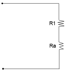
3. Now, take a look on the next circuit figure below.  The circuit was already simplified into series circuit and we can already get the total resistance of the circuit.

Equivalent Simplified Circuit
The total resistance of the given circuit based on the simplified circuit above would be: Rt= R1 + Ra = 7 + 5 = 12 ohms. Very easy right?

It only means that a complex circuit can be broken down into simplified circuit to get the total resistance Rt = 12 ohms.

I will leave the next circuit as your exercise. This is a bit complicated than above circuit problem. The application is still the same. Given that R1= 1 ohm, R2= 2 ohms, R3= 3 ohms, R4= 4 ohms, R5= 5 ohms, R6= 6 ohms, R7= 7 ohms, R8= 8 ohms and R9= 9 ohms. What will be the total resistance of the circuit below?

Exercise: What is the total resistance of the given circuit? 
After further simplication, I found out that the total resistance of the given circuit above is 11.10 ohms. Did you get the same answer? If not, you may leave your comment below and let's discuss...

Since you've already understand the concept of series-parallel circuits, it is now time to move fast on another topic on my next post. This is already the Part 3 and would be dealing with bridge resistor circuits.

Stay tune!

Cheers!
readmore »»   http://img.ezinemark.com/imagemanager2/files/30004252/2011/11/E10.jpg

Series-Parallel Circuits- Part 1

It's been a long time ago when I posted my last topic about Electric Circuits.  Though its very difficult to have time to write a topic for this blog, this site will always be alive for you. I would like to thank first those who have subscribed to this blog.

Well, let's talk about another basic topic about Basic Electrical Engineering. This is about Series-Parallel Circuits. For those who are just new with this site, you can surely catch up with my previous post at Electrical Engineering Syllabus that I've provided last time.

Circuits can be connected into complex circuits consisting of three or more resistors. One part of the circuit is in series and the other part could be connected in parallel. This connection is called the Series-Parallel Circuits.

There are two types of series-parallel connections: the first one is the resistance in series with a parallel combination and the other one is the series in which the parallel combination have a series of resistances. Let's see the figure below for better understanding of this theory.

a. This is a series resistances with a parallel combination.
b. This is a series resistance and series of resistances in a parallel combination.
Take for example you have three lamps to be connected in a source of a battery. There are two ways that you can connect it. The first one is that: connecting the first lamp connected in series to the parallel combination of the second and third lamp. The second one is that: first and second lamp is connected is series then connect it parallel to the third lamp.


How to Simplify a Series-Parallel Circuit Connection?

In dealing with series-parallel connection, there's nothing something new formula to be use here except for concept of Ohm's Law.

In terms of simplifying a circuit, all you need to do is to start first with the most complex part before you get the overall resistances of the entire circuit. Take the following steps below as your guide. This is what I've always follow when I was still a student.

1. First, redraw the circuit in a most comprehensive way if necessary. Some circuits looks like complicated at first glance, but if you will redraw it equivalent to the original circuit, you could easily deal with it.
2. Start to simplify the circuit in the complex part. In the parallel combination with branches consisting of two or more resistors in series, start to simplify them by adding its value.
3. Then using the formula of the parallel resistances, get the value of resistances of parallel parts of the circuit.
4. Then, combined the resistances of the entire circuit.

Is it clear? Ok let's proceed...

Let's take a sample figure 2 below:


Using the steps above:

1. You don't need to redraw the circuit above, since it is obviously where to start simplifying the circuit.
2. Simplify the resistance of D and E first using the equivalent resistances in parallel formula. Then, add the combined resistances of D and E to C using the resistances in series formula.
3. Since you already get the value of combined resistances for D and E to C. Then, you may now get the combined resistances of B to D, E and C using resistances in parallel.
4. Get the overall resistance Rt = Ra + R(combined resistances of B, C, D and E).

Now you get the clear understanding of series-parallel circuits. On my next post, I will show you more illustrative examples which were already given in previous Electrical Engineering Board Exams.

Cheers!
readmore »»   http://img.ezinemark.com/imagemanager2/files/30004252/2011/11/E10.jpg

Electric Shock - Save Yourselves!

Its been a long time when I post my last topic here in Learn Electrical Engineering for Beginners. Although the author of this blog is very busy with his life, he's trying to make a post in order to feed his readers with good information.

It's Christmas time! We're expecting that everyone is busy preparing to celebrate this holiday season. In connection to this, accidents are also very prone this holiday season. There are fires, car accidents and a lot more. One of the topic that I would like to stress now is related to my blog which is Electric/Electrical Shocks which is one of the common accident this Christmas Season.

Electric/Electrical Shock is the injury caused by an electrical current passing through the body. The electricity maybe atmospheric (lightning) or man-made (high-voltage transmission and low-voltage lines). Possible injuries include burns and physiological disturbances, which may range from a minor burn to death in severe cases.

What are the common causes?
  • Touching high-tension wires that fall during the storm.
  • Touching an electric socket or worn out cord.
  • Mixing water and electricity.
  • Being struck by lightning. A bolt of lightning carries as many as 30 million volts.
What are the symptoms?
  • Shocking sensations. Numbness or tingling. A change in vision, speech, or in any sensation.
  • Burns or open wounds. These occur where the electricity enters and exits the body.
  • Muscle spasms or contractions.
  • Sudden immobility or fractures. A body part may looked deformed.
  • Interrupted breathing. Irregular heartbeat or chest pain.
  • Seizures.
  • Unconsciousness.
What are the steps to save the victim from electric/electrical shocks?
  1. The victim usually gets stuck to the source of the electricity, and it important that you first separate him from electrical source.
  2. Turn off the power supply switch and disconnect the plug. It's best to simply turn off the main power supply or pull out the fuse. Often, simply turning off the switch may not stop the flow of electricity.
  3. DO NOT touch the victim with your bare hand, or the electric current will pass through you as well.
  4. Water with electrolyte, fruit/vegetable juice should be given to the victim.
  5. If you are barefoot, stand of some clothes or any hand non-conductive material like wood or paper. Make sure that you are not standing on anything that is wet.
  6. Throw a blanket over the victim and try to separate him from the source. Make sure you don't touch him though. You could also use dry, non-conductive material such as wooden broom handle or a chair to separate the victim from the live current, whatever is handy.
  7. Once the victim has been separated, check to see if he is breathing. If breathing has stopped or seems slow, administer CPR immediately.
  8. Cover the victim with a blanket.
  9. If the victim has a burn, remove the clothing from the burned area (unless it's stuck to the skin) and rinse it in cool running water. Cover the burn with a dressing.
  10. Don't apply ice or any ointment or cotton dressing to the burn.
Video related to electric shock first aid:


I hope I had given you another learnings here in Learn Electrical Engineering for Beginners where you are always safety and have knowledge power!

Have a Merry Christmas to everyone! Stay tune for more post.
readmore »»   http://img.ezinemark.com/imagemanager2/files/30004252/2011/11/E10.jpg

What Jobs Awaits for Electrical Engineering Graduates Today?

Let me pause for awhile in posting lectures about Electrical Engineering. Let's have a short talk about the jobs and opportunity awaits for all graduates of Electrical Engineering. Details are fact based on the present situation nowadays and also based on my own personal experienced.

According to National Statistics Coordination Board in the Philippines, unemployment rise from 7.5% of April 2009 to 8.0% of April 2010. The most common rise up of this unemployment rate is because of the newly graduates and one of these are the Electrical Engineering graduates. There are approximately about 1,611 newly graduates in the Philippines (Registered for Electrical Engineering Board Exams)which are expected to be unemployed nowadays. Still grabbing for a new job and opportunity that may suit them.

In U.S. according to Department of Labor's Bereau of Labor Statistics employment grew for Electrical Engineers by 7.8% from the fourth quarter of 2009 to the first quarter of 2010 and now 16.1% above compared to its very low employment last first quarter of 2009. This rise of employment for Electrical Engineering field was due to positive recovery in the U.S. economy.

What's the reason of giving this short comparison to you?

Sad to say, there are only limited of opportunities and jobs for Electrical Engineering here in the Philippines even before during my time way back 1999 after passing my licensure exams. If there is an opportunity or jobs available for Electrical Engineering, the salary or the compensation is very low. Besides, majority of them will required you a minimum two years experience for the position even in the Junior/Cadet Engineering position. That's why other Electrical Engineering graduates like me were all shifted to semiconductor field with attractive compensation and benefits and got their luck related to their field and some aren't got any but dive into last resort which is in the semiconductor operations/processes. Others with no luck in this field grabbed their fate in the call centers- poor engineers...

In connection to this, many Electrical Engineering graduates and experts in the Philippines try their luck to get their job somewhere in US, Australia, Taiwan, Japan, North Korea, Saudi Arabia, Abu dhabi, Kuwait, Dubai, Dammam, Doha, Qatar and sometimes in Canada but quiet limited unlike Saudi Arabia. This means that the Philippine Government should work more on jobs availability most especially to our professionals and experts.  

Take a look on this snapshot in JobStreet: Click on the picture to enlarge.

Electrical Engineering Jobs
If you click "ALL Locations" will appear only limited opportunities in the Phillipines where most of the jobs are in Saudi Arabia in Electrical Engineering.

Take a look on the National Capital Region- Philippines. There are only 97 jobs available below considering this region is the center for opportunities and jobs in any field. Would you think newly graduates of Electrical Engineering could accomodate them all? If you read the qualifications almost none of them offers for newly graduates. If there is, only FEW.


Electrical Engineering Jobs
If you click the National Capital Region, only 97 jobs available with almost no one affers jobs for Electrical Engineering newly graduates.

In my information above, I've already given you a brief idea where most of the jobs and opportunities are coming in for Electrical Engineering field.

So, what are the recommended job positions for a newly graduate of Electrical Engineering?

If you are a newly graduate of Electrical Engineering, it is recommended that you start with a Junior position for your job. Some company are required you to train with their traning program if you are a newly graduate but sad to say, NOT ALL. That's why before you accept their offer, be sure they have some training for you before you start with your current job. Some company have higher expectations with their applicants to have a certain number of years of experience for the job position although you are only a newly graduate. Make sure you won't missed this step.

Some of the known positions for Junior position are Assistant Project Engineer, Junior Design Engineer, Estimates, Electrical Inspectors, Electrical Engineer (Junior Position) and many others related to Electrical Engineering jobs. There are some company that accepts newly Electrical Engineering graduates in the middle position considering if you have an attractive qualifications like:
  • Board Topnochers
  • With above average rating in academic performance or an Honor Student.
  • With certain special skills for their requirements: i.e autocad, excellent communication skills, programming, etc...
  • Experience in certain field they required. Majority one year experience.
Not all newly graduates have these qualifications. If you did not fall under these qualifications. Don't loose HOPE.

There are also some other ways you can explore your skills in Electrical Engineering if this is only your line of interest or the job that you want. You should not depend on what the company could offer job for you. Life must go on. You can also start on your own. For example, building your own repair shop related to electrical machineries, electrical layout job for residential, job for electrical installations etc.

Examples above are the acquired skills during your college days and you can explore these things out. If you think you can shift to other line of interest, you may do so. It really depends where you can find your luck in line with Electrical Engineering jobs. Your own decision is still a MUST.

In my personal experience, I have no luck in finding jobs for Electrical Engineering here in the Philippines because of the limited opportunities. Since, I have other skills that I can explore, I shifted in the field of Semiconductor operations and now in the Supervisory position. This is my decision and choice. But still hoping I can find my luck going abroad for Electrical Engineering jobs if there is any opportunity for me. Skills that I have in Electrical Engineering is still there and I believe I can find my luck anytime if I would pursue.

Before I close this post, here are some of the sites where you can browse for jobs in Electrical Engineering:
P.S. These are the top ten sites I have chosen for you as your reference for finding jobs in Electrical Engineering. These are based on the Google search engine. My mission is to give my readers a high quality content readings for this site especially for beginners.

The list of sites above are subject for change as long as I find other sites that offers good job for electrical engineering. So much for this...

Cheers!
Donny
readmore »»   http://img.ezinemark.com/imagemanager2/files/30004252/2011/11/E10.jpg

Electrical Engineering Tutorial Still Alive?

It's been nine months ago when I stopped making a post here at Electrical Engineeering for Beginners. I had received more comments for some other topics I published. I just want to apologized for my very late response. As you know, I'm not a full time writer of this blog related to Electrical Engineering.

For this 2010 onwards, I will be making my own website about Electrical Engineering. But that will depend on my time since there are no other support I'm receiving to complete this course outline. As of now I'm busy learning an HTML or the Hyper Text Markup Language and CSS or the Cascading Style Sheets to make a website of my own. Besides, I'm a full time worker in one of the semiconductor company where all my time are being spend only to support my family. For all of you readers out there, good news! this Online Electrical Engineering tutorial will  resume on September 2010.

I will continue making a post about Electrical Engineering topics from where I stopped. This blog is now ranking well in Google SERP's which makes me to inspire because it's now PR4 which beats other big sites out there. This will push me helping out our young wanna be Electrical Engineering students today. I would like to thank those who are continue subscribing to this site though it's not been updated for a long time. Now, its your turn to open your laptop and see my two to three times post per week.

More things to clarify out....

I also received an email about this blog was being nominated as Top Blogs conducted by other big sites out there. Ok, well then there are you again links that would like to enter my site in order to have a one way link. You are encouraging me to put your badge to my site containing your links. I checked your site and it's only PR0. Well I'm sorry, but I refused to put your badge to my site. I would like to have a quality links to my site. I just only link to higher PR sites related to Electrical Engineering.

There are also some concerns that I would like to clarify to my readers out there. One time, I received an email requesting me to post about a topic related also to Electrical Engineering. Ok, I will just make a post for your request if there are more requesting for that particular topic.

I also received an emails on how to pass Electrical Engineering board exam. They are also asking me on how to get some manuals or review materials. Well, my advice to you is to enroll yourselves to any known Electrical Engineering Review Centers. In the Philippines, the well known Review Center is the Powerline. This is where I took my review and refresher. One thing that you should put in your mind especially to our Electrical Engineers wanna be. It's not on the review center that matters most, its on how you really understand the principles behind Electrical Engineering. Review Centers will just only give you the technique. Your knowledge is still that matters most here and your confidence on how you will pass your Electrical Engineering Board. To those who are new to this site. You may read my post here:

So much for that, I also received an email on exchanged links to other Electrical Engineering sites. Today, my decision is to stop having an exchanged links because Google will detect my site as spam. I'll better do a high quality content to sustain my SERP. Please stop sending me an email for exchanged links. I only do for one way link.

Now, how do I convinced you to come back to my site?

First, Learning Electrical Engineering keyword have a Global Monthly Search of 3,600. Not too bad to build this site. Advertising competition is only medium.

See this: keyword for "Learning Electrical Engineering"


In Google Search Engine, this site is still number one considering nine months without post or update. Take a look on the other side below:


In Yahoo, Learn Electrical Engineering is still No.3 first page for the mentioned keyword. Considering my site is only hosted free, it also rank well with those mentioned big search engines. You can still find this site easily. Ranking well in search engines means this site has a higher authority and with good quality contents over the other.

For my readers out there, please help me to continue this mission of teaching online for Electrical Engineering. I want to optimized my site with a most competitive keyword "Electrical Engineering". I hope I can still make it to the top.

Stay tune for more updates here in Learn Electrical Engineering for Beginners.

Cheers!
Donny
readmore »»   http://img.ezinemark.com/imagemanager2/files/30004252/2011/11/E10.jpg