There have been a few questions on how the ignition system for the new 3600lb rocket works, but first a little design history. At the beginning of the gross weight increase project, we knew we were going to have to increase the size and likely the weight of the parachute. This necessitated a design change to the rocket to also make it bigger and more powerful to pull that heavier parachute out of the bucket.
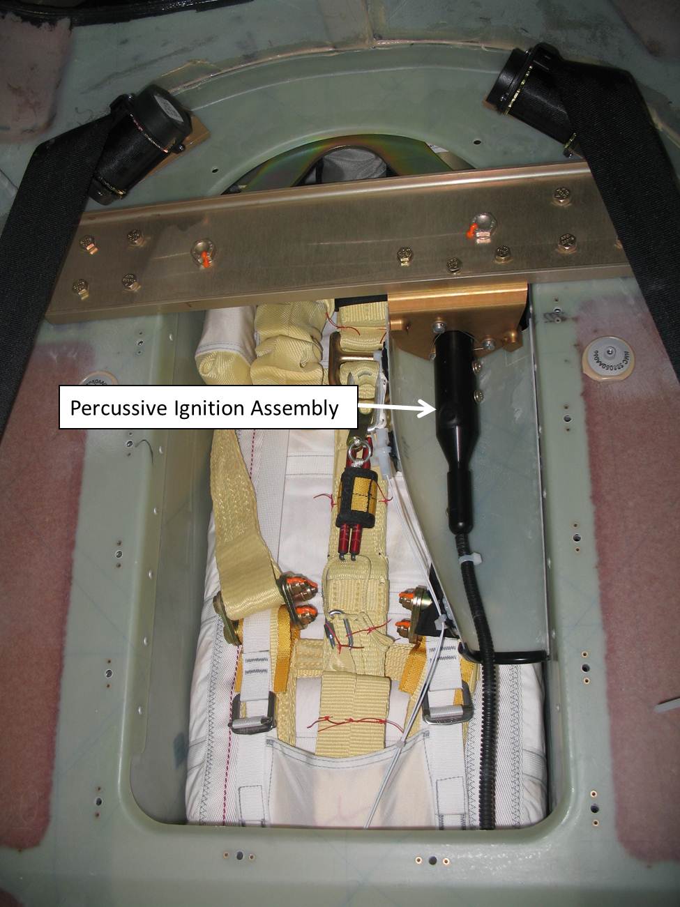
As we began to look into the size and placement of the rocket it quickly became apparent that there just wasn't enough room to fit the new rocket in there. The existing percussive ignition system located at the bottom of the rocket takes up quite a bit of room, so there was nowhere for the new rocket to really grow.
 |
| Original Rocket and Igniter Installation |
By going to an electric ignition system, we could significantly shorten the ignition portion of the system, and allow for a taller rocket. Going to this electric ignition system also allows us to go to a top down ignition which improves the ignition sequence of the propellant especially for longer rockets.
 |
| New Rocket and Igniter |
So now that we had a design that would physically fit into the bucket, we now had to consider several other design criteria. We wanted the ignition sequence from the pilots perspective to be the same. Thus we wanted to keep the same red handle, and the same firm pull required from the existing system. To do this, we kept the handle and the cable exactly the same, and the cable leads to a mechanical switch at the rocket, exactly as in the existing system. The cable is electrically isolated from the switch to prevent the possibility of induced current in the cable during a lighting strike from igniting the rocket.
 |
| Mechanical Switch |
The mechanical switch works the same was as the existing design in that the activation cable pulls down on the plunger compressing the spring until the ball bearings are released and the plunger makes contact with the gold plated connectors and completes the circuit.
So with the rocket in the bucket, and the handle and cable design set, we could focus on the electrical connection. The electrical connection to the mechanical switch had to come from dual sources for redundancy and be "always on" no matter what state the alternators, bolster panel switches, or circuit breakers were in.
This led us to design the system to tie directly to the two batteries. Battery 1 at the front of the airplane and Battery 2 which is actually just below the rocket. Separate harnesses come directly from both batteries and attach to the mechanical switch. When the red handle is pulled, the mechanical switch is triggered which closes the circuit and ignites the rocket.
 |
| Rocket Wiring |
From the switch, we have to get the electricity to the top of the rocket where the igniter is. There also needs to be a way to separate the rocket from the wiring after the rocket is launched. This is done through the use of a frangible link.
 |
| Electrical Connections at the Top of the Rocket |
The igniter at the top of the rocket contains a squib that is used to ignite the rocket. The squib is installed inside the igniter body which protects the squib from damage during the extraction sequence. This squib requires 10 amps for 10 milliseconds to fire. It is not susceptible to static electricity and it is protected from direct and indirect lightning.
 |
| Squib Body After Testing |
So what started as a "simple" problem of fitting a larger rocket into the bucket, became a much more involved design change. The resulting design however is extremely robust and reliable just like its predecessor.