Network Analysis for Electric Circuits

Network Analysis for electric circuits are the different useful techniques related to several currents, emfs, and resistance voltages in such circuit. This is somewhat the collection of techniques of finding the voltages and currents in every component of the network. Some of those techniques are already mentioned in this online tutorial of Electrical Engineering.

There are six remaining useful techniques that we are going to learn. The practical example of each analysis will be given in my next post. This is for you to comprehend first what each theory is all about. So, let's begin the first useful technique in analyzing network. 

Thevenin's Theorem

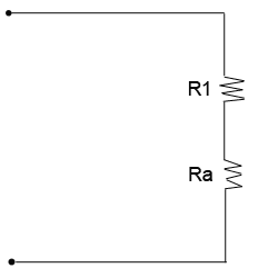
Consider the figure below which schematically represents the two-terminal network of constant emf's and resistances; a high-resistance voltmeter, connected to the accessible terminals, will indicate the so called open circuit voltage voc. If an extremely low-resistance ammeter is next connected to the same terminals, as in fig.(b), which is so called the short-circuit current isc will be measured.

Test circuits for Thevenin's Theorem
Now the two quantities determined above may be used to represent an equivalent simple network consisting of the single resistance RTH, which is equal to voc/isc. If the resistor RL is connected to the two terminals, the load current of the circuit will be

IL = voc / RTH+RL---------------> equation no.1

The analysis leading to the equation no.1 above was first proposed by M.L. Thevenin the latter part of the nineteenth century, and has been recognized as an important principle in electric circuit theory. His theory was stated as follows: In any two-terminal network of fixed resistances and constant sources of emf, the current in the load resistor connected to the output terminals is equal to the current that would exist in the same resistor if it were connected in series with (a) a simple emf whose voltage is measured at the open-circuited network terminals and (b) a simple resistance whose magnitude is that of the network looking back from the two terminals into the network with all sources of emf replaced by their internal resistances.

Thevenin's Theorem has been applied to many network solutions which considerably simplify the calculations as well as reduce the number of computations.

Norton's Theorem

From the previous topic above, it was learned that a somewhat modified approach of Thevenin was formulated. This modified approach is to convert the original network into a simple circuit in which a parallel combination of constant-current source and looking-back resistance "feeds" the load resistor. Take a look on the figure below


Norton's equivalent circuit
Take note that Norton's theory also make use of the resistance looking back into the network from the load resistance terminals, with all potential sources replaced by the zero-resistance conductors. It also employs a fictitious source which delivers a constant current, which is equal to the current that would pass into a short circuit connected across the output terminals of the original circuit. 

From the fig (b) above of Norton's equivalent circuit, the load current would be

IL = IN RN / RN+RL ---------------> equation no.2

Superposition Theorem

The theorem states like this: In the network of resistors that is energized by two or more sources of emf, (a) the current in any resistor or (b) the voltage across any resistor is equal to: (a) the algebraic sum of the separate currents in the resistor or (b) the voltages across the resistor, assuming that each source of emf, acting independently of the others, is applied separately in turn while the others are replaced by their respective internal values of resistance.

This theorem is illustrated in the given circuit below:

Illustration of Superposition Theorem
The original circuit above ( left part ) have one emf source and a current source. If you like to obtain the current I which is equal to the sum of I' + I"using the superposition theorem, we need to do the following steps:

a. Replace the current source Io by an open circuit. Therefore, an emf source vo will act independently having a current I' as the first value obtained when the circuit computed.

b. Replace emf source vo by a short circuit. This time Io will act independently and I" now will be obtained when the circuit computed.

c. The two values obtained ( I' and I") with emf and current source acting independently will be added to get I = I' + I"

Maxwell's Loop (Mesh) Analysis

The method involves the set of independent loop currents assigned to as many meshes as exists in the circuit, and these currents are employed in connection with appropriate resistances when Kirchhoff voltage law equations are written. Take a look on the given circuit below.

Given circuit can be analyze using mesh method
The given circuit above have two voltage sources V1 and V2 are connected with a five-resistor network in which there are two loop currents i1 and i2. Observe that they are shown directed clockwise, a convention that is generally adopted for convenience. The following Kirchhoff's voltage-law may now be written as:

  -V1 + i1R1 + R3(i1-i2) + i1R2 = 0     (loop 1)
  -V2 + i2R5 +R3(i2-i1) + i2R4 = 0     (loop 2)

You may simplify the equations by using the simple algebra. This will be well explained on my next post for more practical examples of Network Analysis.

Nodal Analysis

For this analysis, every junction in the network that represents a connection of three or more branches is regarded as a node. Considering one of the nodes as a reference or zero-potential point, current equations are then written for the remaining junctions, thus a solution is possible with n-1 equations, where n is the number of nodes.

There are three basics steps to follow when using nodal analysis

a. Label the node voltages with respect to ground.
b. Apply KCL to each of the nodes in terms of the node voltages.
c. Determine the unknown node voltages by solving simultaneous equations from step b.

Take a look on the snapshot on how nodal analysis is being done. This is illustration by Stephen Mendez.  Don't worry I will give you the technique on my next post on how to solve nodal analysis.

Note: In the snapshot below, he used conductance which is G = 1/R.


The Nodal Analysis Snapshot

Millman's Theorem

Any combination of parallel-connected voltage sources can be represented as a single equivalent source using Thevenin's and Norton theorems appropriately. This can be illustrated as :


This is Millman's Theorem
The formula above can be written as:

VL = V1/R1 + V2/R2 + .....Vn / Rn 
       -------------------------------
        1/R1 + 1/R2 + ......1/Rn +  1/RL

where:

V1, V2, V3... Vn  are the voltages of the individual voltage sources.
R1, R2, R3... Rn  are the internal resistances of the individual voltage sources.

Vout or VL= load voltage
RL    = load resistor

I think this is enough for today. Don't forget to read my next post for more  practical examples regarding Network Analysis/Theorems.

Cheers!
readmore »»   http://img.ezinemark.com/imagemanager2/files/30004252/2011/11/E10.jpg

What Is Electric Power?

If we are going to recall our Physics subject, it is said that whenever a force is applied that causes motion the work is said to be done. Take a look on the illustration below:

Forces that work is done and  forces not doing work.
The first figure shown above are combination of forces which work is done and forces which work is not done. (a)The picture in which the shelf is held under tension does not cause motion, thus work is not done. (b) The second picture in which the woman pushes the cart causes motion, thus the work is done. (c) The man applied tension in the string is not working since as there is no movement in the direction of the force. (d) The track applied horizontal force on the log is doing work.

The potential difference between any two points in an electric circuit, which gives rise to a voltage and when connected causes electron to move and current to flow. This is one of a good example in which forces causing motion, thus causing work to be done.

Talking about work in electric circuit, there is also a electric power which is the time rate of doing work done of moving electrons from point to point. It is represented by the symbol P, and the unit of power is watt, which is usually represented by the symbol W. Watt is practically defined as the rate at which work is being done in a circuit in which the current of 1 ampere is flowing when the voltage applied is 1 volt.

The Useful Power Formula

Electric Power can be transmitted from place to place and can be converted into other forms of energy. One typical energy conversion of electrical energy are heat, light or mechanical energy. Energy conversion is what the engineers really mean for the word power.

The power or the rate of work done in moving electrons through a resistor in electric circuit depends on how many electrons are there to moved. It only means that, the power consumed in a resistor is determined by the voltage measured across it, multiplied by the current flowing through it. Then it becomes,

Power = Voltage x Current
Watts  = Volts x Amperes

P = E x I  or P = EI ------> formula no.1

The power formula above can be derived alternatively in other ways in terms of resistance and current or voltage and resistance using our concept of Ohm's Law. Since E=IR in Ohm's Law, the E in the power formula above can be replaced by IR if the voltage is unknown. Therefore, it would be:

P = EI
P = (IR)I or P = I2R ------------> formula no.2

Alternatively if I = E/R in Ohm'Law, we can also substitute it to E in the power formula which is terms of voltage if the resistance is unknown.

P = EI
P = E(E/R) or P = E2R ---------> formula no. 3

For guidance regarding expressing of units of power are the following:
a. Quantities of power greater than 1,000 watts are generally expressed in (kW).
b. Quantities greater than 1,000,000 watts are generally expressed as megawatts (MW).
c.  Quantities less than 1 watt are generally expressed in (mW).

The Power Rating of Equipment

Most of the electrical equipment are rated in terms of voltage and power - volts and watts. For example, electrical lamps rated as 120 volts which are for use in 120 volts line are also expressed in watts but mostly expressed in watts rather than voltage. Probably you would wonder what wattage rating all about.

The wattage rating of an electrical lamps or other electrical equipment indicates the rate at which electrical energy is changed into another form of energy, such as heat or light. It only means the greater the wattage of an electrical lamp for example, the faster the lamp changes electrical energy to light and the brighter the lamp will be.

The principle above also applies to other electrical equipment like electric soldering irons, electrical motors and resistors in which their wattage ratings are designed to change electrical energy into some forms of energy. You will learn more about other units like horsepower used for motors when we study motors.

Take a look at the sizes of carbon resistors below. Their sizes are depends on their wattage rating. They are available with same resistance value with different wattage value. When power is used in a material having resistance, electrical energy is changed into heat. When more power are used, the rate at which electrical energy changed into heat increases, thus temperature of the material rises. If the temperature of the material rises too high, the material may change it composition: expand, contract or even burn. In connection to this reason, all types of electrical equipment are rated for a maximum wattage.

Carbon resistors with comparative sizes of different wattage ratings
of 1/4 watt, 1/2 watt,1 and 2 watts
If the resistors greater then 2 watts rating are needed, wire-wound resistors are used. They are ranges between 5 and 200 watts, with special types being used for power in excess of 200 watts.


Use wire wound resistors if higher than 2 watts are needed

Fuses

We all know that when current passes through the resistors, the electrical energy is transformed into heat which raises the temperature of the resistors. If the temperature rises too high, the resistor may be damaged thereby opening the circuit and interrupting the current flow. One answer for this is to install the fuse.

Fuses are resistors using special metals with very low resistance value and a low melting point. When the power consumed by the fuses raises the temperature of the metal too high, the metal melts and the fuse blows thus open the circuit when the current exceeds the fuse's rated value. What is the identification of blown fuse? Take a look on the picture below.


This is the good fuse


This is the blown fuse
 In other words, blown fuses can be identified by broken filament and darkened glass. You can also check it by removing the fuse and using the ohmmeter.

There are two types of fuses in use today - conventional fuses, which blow immediately when the circuit is overloaded. The slow-blowing (slo-blo) fuses accepts momentary overloads without blowing, but if the overload continues, it will open the circuit. This slo-blo fuses usually used on motors and other appliances with a circuit that have a sudden rush of high currents when turned on.

Fuses are rated in terms of current. Since various types of equipments use different currents, fuses are also made with different sizes, shapes and current ratings.

Various types of fuses are made for various equipments
Proper rating of fuse is needed and very important. It should be slightly higher than the greatest current you expect in the circuit because too low current rating of fuse will result to unnecessary blowouts while too high may result to dangerously high current to pass.

Later we will be study circuit breaker which is another protective devices for over current protection.


Electrical Power in Series, Parallel and Complex Circuits

The principle of getting the total power of the circuit is just simple. There is no need to elaborate this topic.

The total power consumed by the circuit is the sum of all power consumed in each resistance.

Therefore, we just only sum up all power consumed in each resistance whether it a series, parallel or a complex circuits. Thus,

Pt= P1+P2+P3+Pn watts  ---------->formula no. 4

From the problem in my previous post about complex circuit, try to calculate each power of the resistance and the total power as well. Constant practice always makes you perfect!

Cheers!
readmore »»   http://img.ezinemark.com/imagemanager2/files/30004252/2011/11/E10.jpg

Ohm's Law Series-Parallel Circuits Calculation

To end up the discussion of Series-Parallel Circuits, I would like to post this last one remaining topic which is about Ohm's Law of Series-Parallel Circuits for currents and voltages. I did not even mentioned in my previous topics on how to deal with its currents and voltages regarding this type of circuit connection. 


Ohms Law in Series-Parallel Circuits

Ohm's Law in Series-Parallel Circuits - Current

The total current of the series-parallel circuits depends on the total resistance offered by the circuit when connected across the voltage source. The current flow in the entire circuit and it will divide to flow through parallel branches. In case of parallel branch, the current is inversely proportional to the resistance of the branch - that is the greater current flows through the least resistance and vice-versa. Then, the current will then sum up again after flowing in different circuit branch which is the same as the current source or total current.

The total circuit current is the same at each end of a series-parallel circuit, and is equal to the current flow through the voltage source.


Ohm's Law in Series-Parallel Circuits - Voltage

The voltage drop across a series-parallel circuits also occur the same way as in series and parallel circuits. In series parts of the circuit, the voltage drop depends on the individual values of the resistors. In parallel parts of the circuit, the voltage across each branch are the same and carries a current depends on the individual values of the resistors. 

If in case of circuit below, the voltage of the series resistance forming a branch of the parallel circuit will divide the voltage across the parallel circuit. If in case of the single resistance in a parallel branch, the voltage across is the same as the sum of the voltages of the series resistances.

The sum of the voltage across R3 and R4 is the same
as the voltage across R2.

Finally, the sum of the voltage drop across each paths between the two terminal of the series-parallel circuit is the same as the total voltage applied to the circuit.

Let's have a very simple example of this calculation for this topic. Considering the circuit below with its given values, lets calculate the total current, current and voltage drop across each resistances.


What is the total current, current and voltage across each resistances
 Here is the simple calculation of the circuit above:

a. Calculate first the total resistance of the circuit:

The equivalent resistance for R2 and R3 is:

R2-3 = 25X50/ 25+50 = 16.67 ohms

R total =  30 ohms + 16.67 ohms = 46.67 ohms

b. Calculate the Total Current using Ohm's Law:

I1 = 120V / 46.67 Ohms = 2.57 Amp. Since R1 is in series connection, the total current is the same for that path.

c. Calculating the voltage drop for R1:

VR1 = 2.57 Amp x 30 ohms = 77.1 volts

d. Calculate the voltage drop across R2 and R3.

Since the equivalent resistance for R2 and R3 as calculated above is 16.67 ohms, we can now calculate the voltage across each branch.

VR2 = VR3 = 2.57 Amp x 16.67 ohms = 42. 84 volts

e. Finally, we can now calculate the individual current for R2 and R3:

I2 = VR2 / R2 = 42.84 volts / 25 ohms =  1.71 Amp.
I3 = VR3 / R3 = 42.84 volts / 50 ohms = 0.86 Amp.

You may also check if the current in each path of the parallel branch are correct by adding its currents:

I1 = I2 + I3 = 1.71 Amp + 0.86 Amp = 2.57 Amp. which is the same as calculated above. Therefore, we can say that our answer is correct.


Cheers!
readmore »»   http://img.ezinemark.com/imagemanager2/files/30004252/2011/11/E10.jpg

The Bridge Resistor Circuit

This is already the Part-3 lessons for Series-Parallel Circuits. Today we will be dealing with another type of complex circuit which you do not know yet - particularly for the beginners.

Suppose you have a type of simple circuit below. You will notice that there is an extra resistor of R3 connecting to the two parallel branches of the parallel circuit connection and in such way it was interrupted to the leads of the new resistor. This new resistor (R3) is called a bridge.
R3 is called the Bridge Resistor
 Take a look at the circuit above. If you look at the upper part of R3 resistor, wherein R1, R2 and R3 are all connected together. You will notice a new arrangement of connection. This arrangement from its similarity to the shape of the Greek letter D (delta), is said to be delta connected. Here is the diagram below to see clearly what I'm talking about.
This is the illustrative diagram for delta connection


The equivalent connection of left diagram is
called the Y connection 
 Take a look at the diagram at the left side. If you will devise a circuit shown in the delta connection Ra, Rb and Rc to shaped like a Y (wye). This Y circuit would fit onto the rest of the original circuit in such a way that you could solve its values without difficulty. Look at the diagram (at the left)  in Y connection.

The resistors connected in Y are R1, R2 and R3. Take note that their values must be such that the terminal resistances at N1 and N3 are exactly where they were in the original circuit. The problem now is how would you able to solve the values of R1, R2 and R3 (said to be unknown values) in terms of Ra, Rb and Rc whose values are known.

How to Solve Bridge Resistor Circuit

Lets use again this previous diagram. Then, take note that both circuits must give exactly the same values of resistance across every corresponding pair of terminals. This operation that we'll set is called delta-Y conversion or transformation.

delta -Y conversion
 If you consider the sum of the resistances between N3 and N1, then assume N2 is to be disconnected. In delta combination you will see that between these two points there is a series combination of Rc and Rb in parallel across Ra. You can now express the resistance N3 and N1 applying the knowledge of parallel circuits we have:

Ra (Rb + Rc) / Ra + Rb + Rc

Considering the Y circuit connection above, the total resistance between N3 and N1 is R1 + R3. Then, since we all know that these resistances must be equal, you can now write down the first equation as:

R1 + R3 = Ra (Rb + Rc)/ Ra + Rb + Rc   ---------> EQUATION no. 1

For the remaining terminals, you can exactly do the same way for total resistances between N3 - N2 and between N1 - N2 in terms of Ra, Rb, Rc and R1, R2 and R3. Then, you will get the two remaining equations: 

R2 + R3 = Rc (Ra + Rb) / Ra + Rb + Rc  ---------> EQUATION no. 2

R1 + R2 = Rb (Ra + Rc) / Ra + Rb + Rc  ---------> EQUATION no. 3

Then, do a little algebra from the three equations above to obtain the values in terms of R1, R2 and R3. Finally, we can have the following formula:

R1 = Ra x Rb / Ra + Rb + Rc ------------> Formula no. 1

R2 = Rb x Rc / Ra + Rb + Rc ------------> Formula no. 2

R3 = Ra x Rc / Ra + Rb + Rc ------------> Formula no. 3

The problem below was given in the board exam way back 1997 - two years before my  EE board examination.

(EE April'97) A circuit consisting of three resistors rated : 10 ohms, 15 ohms and 20 ohms are connected in DELTA. What would be the resistances of the equivalent WYE connected load?

Solution:
Just get the pattern of the above formula, this would give us the following:

R1 = 10 X 15 / 10 + 15 + 20 = 3. 33 ohms - answer

R2 = 15 x 20 / 10 + 15 + 20 = 6. 67 ohms - answer

R3 = 10 X 20 / 10 + 15 + 20 = 4.44 ohms - answer


Y to Delta Conversion

For the reverse conversion which is Y to delta conversion considering the given circuit.

Y to delta conversion or transformation

The general idea here is to compute the resistance in the delta circuit by:

R- delta = Rp / R opposite

where: Rp is the sum of the product of all pairs of resistances in the Y circuit and R opposite is the resistance of the node in the Y circuit which is opposite the edge with R- delta. You will have the following formula for you to get the equivalent delta load in terms of Ra, Rb and Rc.

Ra = R1R2 + R2R3 + R3R1 / R2 ---------> Formula no. 4

Rb = R1R2 + R2R3 + R3R1 / R3 ---------> Formula no. 5

Rc = R1R2 + R2R3 + R3R1 / R1  ---------> Formula no. 6

These are the formula that you'll going to use from our future topics since this is already the part of Network Theorems. Don't ever forget it...

Cheers!
readmore »»   http://img.ezinemark.com/imagemanager2/files/30004252/2011/11/E10.jpg

Series-Parallel Circuits- Part 2

This is just the continuation of my post yesterday about Series-Parallel Circuits- Part 1. I've already provided you the steps on how to simplify a simple series-parallel connections. Today, I will give you an example on how to solve that circuit using that steps mentioned before.

The practical example that I will show you below is how to break down a complex circuits to find the total resistance. Refer to figure below:

Circuit Problem for Series-Parallel
Let's say:  R1= 7 ohms, R2= 10 ohms, R3= 6 ohms and R4= 4 ohms. We are required to get the total resistance of the circuit.

Using the steps that previously discussed here. We can redraw an equivalent circuit in a way that we can understand it well. The figure below is the redrawn circuit for the given problem above.

1. Redraw the circuit.

Redrawn Series-Parallel
From the redrawn circuit above. we can now simplify R3 and R4. Lets name it R3-4 = 6+4 = 10 ohms.

2. The next step is by getting the resistance between R2 and R3-4 connected in parallel. The circuit now will be simplify as shown below:

Simplified R3-4 to be combine with R2
Next, we will simplify the R2 and R3-4 using the formula of two resistances connected in parallel. Let's name it Ra= R2 X R3-4 / R2 + R3-4 = 10 x 10 / 10 +10 = 5 ohms.

3. Now, take a look on the next circuit figure below.  The circuit was already simplified into series circuit and we can already get the total resistance of the circuit.

Equivalent Simplified Circuit
The total resistance of the given circuit based on the simplified circuit above would be: Rt= R1 + Ra = 7 + 5 = 12 ohms. Very easy right?

It only means that a complex circuit can be broken down into simplified circuit to get the total resistance Rt = 12 ohms.

I will leave the next circuit as your exercise. This is a bit complicated than above circuit problem. The application is still the same. Given that R1= 1 ohm, R2= 2 ohms, R3= 3 ohms, R4= 4 ohms, R5= 5 ohms, R6= 6 ohms, R7= 7 ohms, R8= 8 ohms and R9= 9 ohms. What will be the total resistance of the circuit below?

Exercise: What is the total resistance of the given circuit? 
After further simplication, I found out that the total resistance of the given circuit above is 11.10 ohms. Did you get the same answer? If not, you may leave your comment below and let's discuss...

Since you've already understand the concept of series-parallel circuits, it is now time to move fast on another topic on my next post. This is already the Part 3 and would be dealing with bridge resistor circuits.

Stay tune!

Cheers!
readmore »»   http://img.ezinemark.com/imagemanager2/files/30004252/2011/11/E10.jpg

Series-Parallel Circuits- Part 1

It's been a long time ago when I posted my last topic about Electric Circuits.  Though its very difficult to have time to write a topic for this blog, this site will always be alive for you. I would like to thank first those who have subscribed to this blog.

Well, let's talk about another basic topic about Basic Electrical Engineering. This is about Series-Parallel Circuits. For those who are just new with this site, you can surely catch up with my previous post at Electrical Engineering Syllabus that I've provided last time.

Circuits can be connected into complex circuits consisting of three or more resistors. One part of the circuit is in series and the other part could be connected in parallel. This connection is called the Series-Parallel Circuits.

There are two types of series-parallel connections: the first one is the resistance in series with a parallel combination and the other one is the series in which the parallel combination have a series of resistances. Let's see the figure below for better understanding of this theory.

a. This is a series resistances with a parallel combination.
b. This is a series resistance and series of resistances in a parallel combination.
Take for example you have three lamps to be connected in a source of a battery. There are two ways that you can connect it. The first one is that: connecting the first lamp connected in series to the parallel combination of the second and third lamp. The second one is that: first and second lamp is connected is series then connect it parallel to the third lamp.


How to Simplify a Series-Parallel Circuit Connection?

In dealing with series-parallel connection, there's nothing something new formula to be use here except for concept of Ohm's Law.

In terms of simplifying a circuit, all you need to do is to start first with the most complex part before you get the overall resistances of the entire circuit. Take the following steps below as your guide. This is what I've always follow when I was still a student.

1. First, redraw the circuit in a most comprehensive way if necessary. Some circuits looks like complicated at first glance, but if you will redraw it equivalent to the original circuit, you could easily deal with it.
2. Start to simplify the circuit in the complex part. In the parallel combination with branches consisting of two or more resistors in series, start to simplify them by adding its value.
3. Then using the formula of the parallel resistances, get the value of resistances of parallel parts of the circuit.
4. Then, combined the resistances of the entire circuit.

Is it clear? Ok let's proceed...

Let's take a sample figure 2 below:


Using the steps above:

1. You don't need to redraw the circuit above, since it is obviously where to start simplifying the circuit.
2. Simplify the resistance of D and E first using the equivalent resistances in parallel formula. Then, add the combined resistances of D and E to C using the resistances in series formula.
3. Since you already get the value of combined resistances for D and E to C. Then, you may now get the combined resistances of B to D, E and C using resistances in parallel.
4. Get the overall resistance Rt = Ra + R(combined resistances of B, C, D and E).

Now you get the clear understanding of series-parallel circuits. On my next post, I will show you more illustrative examples which were already given in previous Electrical Engineering Board Exams.

Cheers!
readmore »»   http://img.ezinemark.com/imagemanager2/files/30004252/2011/11/E10.jpg